
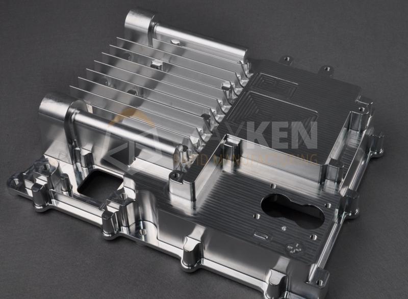
Machining complex aluminum parts demands more than 5 axes; it requires adaptive strategies. Manufacturers often face non-uniform walls, deep internal cuts, and thin ribs. 5-axis CNC machining opens access to overcome these problems, but still geometry sets strict constraints. Although fast feed rates cut time, but increase heat thresholds. Besides, the wrong tilt angle can stress the cutter.
In machining cycles, the workpiece behaves differently from models. Flexure, chip evacuation, and coolant behavior shift with tool angles. You cannot run static tilt angles across deep holes/contours. Sharp overhangs entail dynamic tilt and segmenting. So, one fixed strategy rarely suits all parts of the zones.
If the fixture bends thin sections, it affects the geometry later in the process. Aside from this, if tilt sync is not uniform, blend lines are likely to appear. Even in high-speed roughing, deflection persists without adaptive toolpaths aligned to material flow. You must tune the spindle speed to chip thickness zones. A smart 5-axis strategy adapts across all geometries.
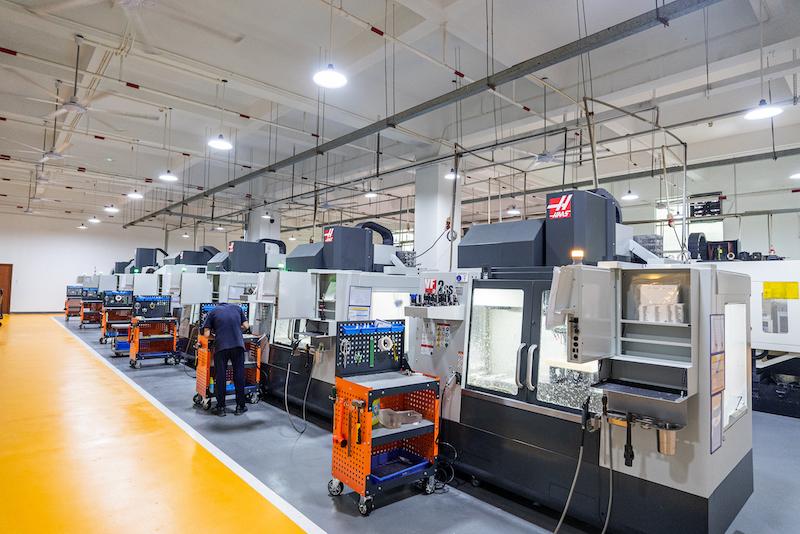
At WayKen Manufacturer, our engineers handle complex aluminum parts using advanced aluminum machining services. Whether you need tight-tolerance parts or multi-axis cuts, we can deliver. Our team handles dynamic toolpaths and ensures the part meets strict structural and visual requirements.
In this article, we will explore practical 5-axis machining strategies for aluminum parts. These methods help you machine complex parts with high precision and control.
Fixturing and Repositioning Strategy for Multi-Side Machining
Fixturing repeatability and load control are imperative for reliable multi-side machining. Variable setups cause compound alignment errors. These usually appear when referring to rotated views. The local geometries must remain intact when your fixture isolates the cutting force. It requires complete planning of support, sequencing, and access.
- Support Where the Material Can Handle the Pressure
You need to add clamps at points where the structure can hold a load. Ribs are weak areas. These bend even under minimal force. So, use the thickest regions as primary contact points. Besides, never clamp near the expandable areas.
Soft jaws must be used in deep pockets. These help distribute the uniform pressure in a balanced way. Typically, intricate geometries require profile matching to fit in contact. Otherwise, vibration and spring-back can ruin your part finish. Your fixture must be in line with the cut forces.
- Reduce Repositioning by Planning Axis Access Early
While repositioning increases cycle time, it also safeguards geometric integrity across multiple setups. Try to reach all sides using rotary table access. This reduces setups and human error. Alignment must be done manually again during unmounting conditions.
Fixed-axis views come first in building your CAM strategy. Find out what you can reach within zero repositioning. When you have to reposition, tight-tolerance locators or pins should be used. This makes realignment viable through the last pass.
- Make Design Fixtures Capable of Dealing with both Force and Heat
The 5-axis roughing imposes pressure on your fixture. The heat accommodation, particularly during aluminum machining, modifies part behavior. In the event of the part enlargement, clamps must absorb the movement. The stiff clamping without allowance results in warp or causes surface shift.
Use relief cuts and compliant stops in key locations. The part should move slightly and not lose its reference point. Moreover, confirm that your fixture absorbs radial tool pressure. Aluminum expands roughly 23 microns per meter per degree Celsius. Over long parts, a 10-degree shift can shift fixtures’ positions by 200 microns or more.
Managing Chip Evacuation in Deep Cavities
Milling deep holes in aluminum components often comes with a set of challenges. Because chips accumulate more rapidly. They deteriorate the tool life and part surface finish. Without evacuation, the chatter or tool breakage tends to occur from recutting and heat. Here is how experienced shops maintain control:
Use Coated Tools with High Helix Angles: High-helix cutters allow rapid removal of chips from pockets. These, combined with smooth flutes and coatings, minimize chip adhesion. Usually, it is important in soft aluminum grades like 6061, which smears when loaded, unlike 7075, which holds form but cuts harder.
Program Entry Paths That Clear Early Material: It is always advised to open an exit way before driving deeper. Chips are caught fast in ramping into closed pockets. To break confinement early in the cycle, use initial slots and adaptive spirals.
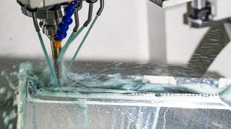
Apply Through-Spindle Coolant at Controlled Pressure: Flooding is not an effective solution in long, narrow cavities. Through-spindle, coolant reaches the end of the tool and sweeps away debris automatically. However, there must be adequate pressure. This not only cools but also injects chips.
Use Minimum Quantity Lubrication (MQL) for Dry Zones: MQL is useful in places that cannot be reached by coolant. It not only cools down the tool edge, but also renders chips less sticky. So, for long-reach tools in small-diameter cuts, it is really useful.
Schedule Toolpath Pauses or Retracts for Chip Clearing: Chip packing problems arise due to longer tool engagement. The program has short retracts or dwell breaks to allow chips to escape. Tool binding can be avoided even by 1 to 2 second pauses at depth.
Orient the Cavity to Gravity When Possible: 5-axis rotation allows you to slope the cavity opening down. Chips are evacuated better through gravity. Repositioning the part even slightly can reduce chip-trap zones.
Using Adaptive Toolpaths to Handle Complex Geometries Efficiently
Adaptive toolpaths minimize tool strain in tight spaces. They hold constant engagement along complex wall profiles. This helps avoid chatter, improves accuracy, and prevents tool breakage. It is recommended to use 3-flute, high-helix tools with polished flutes and micro corner radii under 0.5 millimeter for deep-pocket cuts.
Moreover, using adaptive toolpaths enables fewer retractions and uniform tool transitions. Adaptive linking keeps motion active across multiple cut zones. As a result, the idle time is reduced, and spindle load balance is improved.
In thin-walled areas, it is optimum to balance the radial and axial load. Use a lower stepover with lighter cutting passes. It helps you avoid deflection and protects the final part geometry.
In addition, these tool paths adapt to surface change without overcutting. They allow deeper cuts without impacting the fine part features. For aluminum grade 7075, a 12 to 15 thou radial stepover at 60 to 80% spindle load keeps tool deflection within 3 microns.
Conclusion
5-axis machining of aluminum requires more than a setup. It demands coordinated strategies that maintain and align tool dynamics with geometry. Optimum machining depends on effective planning, not just machine motion range.
Stable fixturing supports thin sections without clamping distortion. Repositioning should serve to access, not compensate for, weak setups. It is recommended to avoid transitions through full reach programming wherever possible.
In deep cavities, chip evacuation controls surface finish quality and wear. The coolant strategy, flute design, and pass sequencing must be aligned. Besides, poor evacuation forces recuts, causes heat buildup, and damages the tool.
In addition, adaptive toolpaths stabilize forces across variable cross-sections. They improve the finish on thin webs and internal ribs. Additionally, they reduce tool deflection and harmonics.
Effective aluminum machining depends on the integration of above mentioned practices, not isolated techniques. Toolpaths, fixtures, and material behavior must support each other. That synergy produces predictable results in complex 5-axis machining.
